
Views: 0 Author: Site Editor Publish Time: 2026-08-17 Origin: Site


Clear automotive lighting components demand flawless optical clarity and strict dimensional stability. Headlight lenses, taillights, and complex light guides face immense scrutiny during vehicle manufacturing. Polycarbonate (PC) and PMMA are highly viscous resins. They remain extremely sensitive to shear stress during the injection molding process. Poor tooling design inevitably results in severe cosmetic defects and unacceptable scrap rates. Burn marks, splay, and structural weld lines ruin expensive optical parts daily.
We must reframe gating and exhaust layouts entirely. Treat them as primary drivers of production yield rather than mere technical necessities. Master these critical tooling elements to ensure unit cost efficiency and regulatory optical compliance. This comprehensive guide explores advanced strategies to eliminate optical defects completely. You will learn how predictive simulations and strategic exhaust placements secure long-term manufacturing success. Read on to master the precision engineering behind flawless clear plastic components.
Strategic gate placement minimizes shear stress and prevents optical distortion (birefringence) in clear PC and PMMA lenses.
Precise automotive lighting mold venting eliminates the "diesel effect" (burn marks) and trapped gas without causing flash.
Predictive mouldflow analysis is a mandatory validation step before cutting steel to ensure optimal flow progression and weld-line placement.
Achieving and maintaining an SPI A-1 mould finish requires venting systems that prevent gas-induced pitting on the tool surface.
Evaluating a tooling partner requires verifying their specific experience with optical-grade resins and highly polished molds.
Unlike structural internal components, clear lenses dictate vehicle aesthetics and photometric safety standards. Agencies like DOT and ECE mandate flawless light transmission globally. You cannot tolerate any optical distortion on these critical safety parts. We often see severe manufacturing defects tied directly to poor tooling design. Designing an automotive light lens mould correctly prevents these costly issues from the start. High shear at the gate creates flow marks and cloudy haze. Compressed, superheated trapped gas causes severe burn marks. Weld lines create structurally weak and optically disruptive areas. These happen when multiple flow fronts meet awkwardly during the filling phase.
Reactive mold modifications pose enormous financial risks. Welding and re-cutting steel costs thousands of dollars per iteration. It also delays critical vehicle production launches significantly. Getting the design right before manufacturing protects your profit margins. Zero-defect tolerance defines the modern automotive lighting industry. Any trapped gas or structural flaw compromises the entire headlamp assembly. Manufacturers reject parts showing even minor birefringence or haze. We must prioritize initial tool engineering to avoid catastrophic scrap rates later. Tooling engineers carry the direct responsibility for ensuring long-term yield.
Common Optical Lens Injection Defects and Causes
Defect Type | Visual Impact | Primary Tooling Cause |
|---|---|---|
Flow Marks / Haze | Cloudy streaks near the injection point | High shear stress from undersized gates |
Burn Marks | Black or brown scorched edges | Trapped air igniting (diesel effect) |
Weld Lines | Visible lines disrupting light paths | Improper gate location or multiple flow fronts |
Sink Marks | Surface depressions distorting optics | Poor gate placement preventing cavity packing |
Gate size and type dictate the flow velocity of high-viscosity resins like polycarbonate. High shear alters the material refractive index. This alteration causes severe optical distortion in final parts. You must minimize shear stress during injection to preserve total clarity. We rely on strategic gate sizing to maintain steady flow fronts. If you force viscous plastic through tiny gates, friction spikes rapidly. The resin degrades thermally before it even fills the cavity completely. This thermal degradation destroys the mechanical and photometric properties of the lens.
Optimal Gate Types for Clear Parts:
Fan Gates and Edge Gates: These distribute plastic evenly across wide lenses. They reduce flow marks efficiently by spreading the resin front outward in a uniform wave.
Valve Gating (Hot Runners): We find these ideal for large headlamp lenses. They control pressure precisely and eliminate ugly gate vestige. They also sequence flow fronts to hide weld lines effectively.
Placement logic dictates how resin fills the tool cavity. Flow must always progress from the thickest section to the thinnest. This approach maintains holding pressure perfectly during the cooling phase. It prevents cosmetic sink marks and internal vacuum voids. We always place gates in thicker regions to pack out the cavity properly. If you gate into thin areas, the resin freezes too fast. The thicker sections then shrink and create internal voids. These voids act like tiny unwanted prisms. They destroy the photometric performance of the entire lens. A well-designed gating strategy prevents birefringence and internal stress.
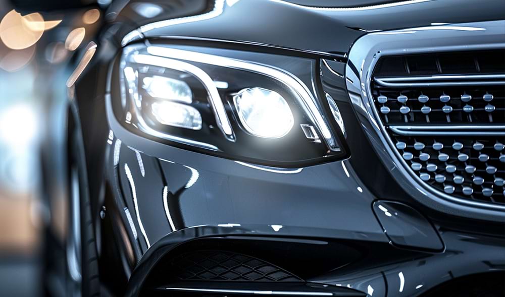
Proper tooling evacuates air from the cavity at the exact rate resin fills it. If air cannot escape, it compresses rapidly ahead of the flow front. This trapped air superheats and ignites the resin instantly. We call this combustion the "diesel effect." It causes ugly burn marks and damages the tool steel permanently. Implementing precise automotive lighting mold venting prevents this combustion entirely. You must machine these exhaust paths with extreme accuracy using advanced EDM equipment.
Venting Specifications by Material
Material | Standard Depth (mm) | Land Length (mm) | Relief Depth (mm) |
|---|---|---|---|
Polycarbonate (PC) | 0.03 - 0.05 | 1.0 - 1.5 | 1.0 - 1.5 |
PMMA (Acrylic) | 0.02 - 0.04 | 1.0 - 1.2 | 1.0 - 1.5 |
Standard depth constraints for PC usually range from 0.03mm to 0.05mm. This critical dimension allows gas escape while preventing plastic flash. Vent land lengths must remain short to reduce exhaust resistance. Relief channels then dump the exhaust gas safely into the atmosphere. We must perform regular maintenance to keep these channels clear of outgassing residue. Clogged channels fail immediately.
Advanced designs move beyond the simple parting line. We include exhaust channels at ejector pins and core pins. Blind pockets trap air easily and cause short shots. We use localized porous steel inserts for these hard-to-reach areas. Porous steel features microscopic interconnected holes. It allows gas to bleed through the metal itself while blocking the resin. This eliminates the diesel effect in complex geometric features seamlessly.
Predictive engineering beats reactive troubleshooting every single time. You must validate designs virtually before cutting any expensive steel. Conducting a thorough mouldflow analysis serves as a non-negotiable risk mitigation tool. It guarantees optimal flow progression and predictable shrinkage rates. Clear lenses cannot hide internal stresses or surface blemishes. We rely entirely on simulation software to catch design flaws early.
Key Evaluation Metrics in Simulation:
Fill Time and Pressure Drop: Ensures the molding machine packs the part completely without exceeding available tonnage limits.
Air Trap Prediction: Identifies exact locations requiring machined exhaust channels before tooling begins.
Weld Line Mapping: Simulates flow fronts to push weld lines into non-cosmetic areas. You can often hide them behind bezels or internal housings.
Success criteria remain incredibly strict for optical components. The simulation must match the proposed physical layout precisely. It must account for the specific rheology of your chosen optical resin. Polycarbonate exhibits unique viscosity curves under high shear. We analyze the shear heating results closely during the simulation phase. If the software shows excessive shear, we modify the gate sizing immediately. You save weeks of rework by iterating in the software first. This predictive step ensures a remarkably smooth transition into mass production.
Flawless light transmission requires a pristine, mirror-like tool surface. You must achieve a Grade #3 diamond buff on the cavity steel. This rigorous process defines the demanding SPI A-1 mould finish required for clear lenses. There is a direct, undeniable link between exhaust efficiency and surface polish longevity. Inadequate exhaust causes acidic gas buildup during the injection cycle. This corrosive gas etches and pits the highly polished tool surface over time.
The chemical attack destroys the mirror finish rapidly. You will soon see a hazy, milky appearance on your molded lenses. Maintenance realities hit hard when initial designs fail. You face severe production downtime to clean and restore the tool. Constantly repolishing molds due to poor design destroys your profitability entirely. Polishing a complex headlight cavity takes days of skilled manual labor.
Furthermore, repolishing removes microscopic layers of steel. Over time, removing this metal changes the lens geometry slightly. This subtle change ruins the dimensional stability needed for DOT compliance. Protect your investment through proactive gas evacuation. Efficient channels keep corrosive byproducts flowing out of the tool continuously. This preserves the pristine finish and extends the maintenance interval significantly. Good engineering protects the steel.
Choosing the right tooling partner dictates your project success completely. Assess their optical experience carefully during the initial vetting process. Do they have a proven track record with optical-grade PC and PMMA? General automotive experience is rarely sufficient for clear lighting parts. You need specialists who deeply understand light guides and thick lenses. Ask them how they handle birefringence and internal stress.
Demand complete design transparency from day one. They must provide full DFM (Design for Manufacturability) reports prior to issuing any purchase order. Ensure they understand proper mould venting strategies intimately. The DFM should clearly outline draft angles, wall thickness variations, and optimized cooling channel layouts. Uneven cooling causes warp, which distorts optical performance.
Evaluate their internal tooling infrastructure next. Do they possess high-speed CNC and precise EDM equipment? You need these machines for tight-tolerance machining and flawless surface finishes. High-speed spindles exceeding 30,000 RPM are mandatory for optical inserts. Shortlist manufacturers who treat gating and exhaust as interconnected systems. They should never view them as mere afterthoughts. Ask them for documented case studies of similar lighting projects. Review their past simulation reports to verify their engineering rigor. A capable partner will challenge your part design actively to secure optimal photometric results.
Gating and exhaust systems dictate the success or failure of clear automotive lighting components. You cannot cut corners on these crucial tool design elements. High-quality tooling requires an upfront investment in precise design and predictive simulation. This strategic effort secures long-term production scalability and strict optical compliance.
Optical-grade polycarbonate and PMMA demand respect during processing. Properly sized gates manage shear stress effectively. Precisely machined exhaust channels prevent catastrophic burn marks and preserve the mirror finish. When these elements work together, you achieve exceptional yield rates.
Audit your prospective mold maker’s DFM capabilities closely today. Review their simulation data thoroughly before committing to any tooling capital. Demand engineering excellence early to ensure flawless, profitable parts later.
A: Fan gates or sequenced valve gates are typically preferred. They reduce shear stress, prevent flow marks, and manage the high viscosity of optical-grade polycarbonate effectively. Fan gates distribute the melt evenly, while valve gates allow precise flow control for larger lenses.
A: For standard optical polycarbonate, vent depths usually range between 0.03mm and 0.05mm. This dimension is critical: too shallow traps gas, and too deep causes flash. PMMA requires slightly shallower depths, typically between 0.02mm and 0.04mm.
A: Clear lenses cannot hide internal stresses, weld lines, or air traps. Mouldflow analysis predicts these defects virtually, allowing engineers to adjust gate and vent locations before expensive steel is cut. It guarantees optimal filling and packing.
A: Trapped, pressurized gases degrade resin and release corrosive byproducts that pit and haze the mold steel. Proper venting prevents this chemical attack, preserving the highly polished SPI A-1 finish required for clear lenses.
A: No. Automotive lighting mold venting refers to the exhaust channels machined into the injection mold tool to let air escape during manufacturing. Moisture vents (like ePTFE membranes) are physical components added to the final assembled headlight to manage humidity and pressure in the field.


